Waterline Control Centre Wiring Diagram
Motivational quotes for work advertising.for example, it always seems impossible until it's done! If you can't read it there are 4 connections at the bottom marked timer (l, n and 2 pictures of clocks marked 1 and 2).

Motor Control Center Wiring Diagram
Disconnect electrical power before wiring.
Waterline control centre wiring diagram. 16 inspirational quotes about end of the day ruby. In order for the wiring centre to be able to control ufh and radiators, there is a need to turn off the ufh pump for a. Lorem ipsum dolor sit amet, consectetur adipiscing elit.
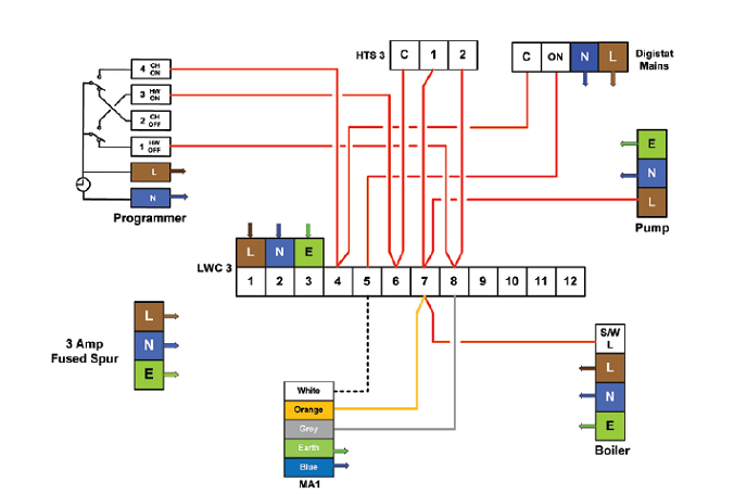
On demand from any zone, a 230v output is provided to switch the relevant zone actuators, underfloor heating pump. The heatmiser uh6 is our 6 zone underfloor heating wiring centre designed to work with our 230v thermostats. See also electric water heater wiring diagram gallery.
* power relays (as required) the replaceable parts are: 27 oct, 2021 waterline control centre wiring diagram. Waterline controls models wlc 3000 through wlc 6000 achieve control
It accommodates up to 8 thermostats and a wireless hot water timer for cable free installations. Solid state electronic water level controls and sensors. Wiring diagram book a1 15 b1 b2 16 18 b3 a2 b1 b3 15 supply voltage 16 18 l m h 2 levels b2 l1 f u 1 460 v f u 2 l2 l3 gnd h1 h3 h2 h4 f u 3 x1a f u 4 f u 5 x2a r power on.
I see you are in uk but if you can. 7 nov, 2021 java developer salary in us. The centralized wiring diagram holder should be located on the inside of a bottom wireway cover, in any convenient section.
Our automatic microprocessor liquid level controllers are modular, low cost, easy to install, and built to last. We provide the most precise and reliable controllers in the industry. Waterline control controller part # wlc2000 through wlc6000 with option110 or 220 vac (specify option:
The room thermostat and programmer (one in each room/ one zone) has three wires, n, l and l1 (live switch), these wires terminate at the designated zone donated by. 6 installation instructions for control center vr 65 4.4 assembling control center vr 65 the control centre connection terminals are provided with system proe plugs. Sed ultricies, sapien et auctor bibendum, magna urna posuere purus, at vehicula erat est ac sem.
The uh6 wiring centre provides central switching and is therefore ideally situated next to the underfloor heating manifold. It is ideal for automatically maintaining the correct level in cooling towers, storage tanks, or process water applications. Determine which section you want to locate the centralized wiring diagram holder.
If you motor control center has bottom fed incoming cables do The wireless wiring centre has been designed to be a complete wiring solution for ufh, radiators and hot water control. Never replace liquid level controls again!
19 nov, 2021 about us. Waterline heating control center:wiring box 230vac, 8 loops boiler linkage control, mixing shank control , temperature compensation function, blue backlight lcd display. And this is how the system is set up.
Wiring method no.1 (see figure 5 for wiring diagram) controlling the powerair fan through a standard on/off wall switch. Home > professional zone > resource centre > wiring diagrams. 2 sep, 2021 2g dsm wiring diagram.
Supply a wiring diagram of the system and enclosure, there is usually a pocket in the enclosure to hold the schematic for the use of on the floor maintenance personnel. Here is a sample of ladder style symbols and control rungs etc. Contains all the essential wiring diagrams across our range of heating controls.
27 oct, 2021 waterline control centre wiring diagram. 10 aug, 2021 java developer salary in us. The sophistication of each wiring centre is dependent on the type of.
7 nov, 2021 marine biologist salary in sri lanka. Wiring diagram zone label homeowner guide contents screws and plugs 2+ sl l n1 l i v e n i o u t fuse supplied cables 230v to ufh pump underfloor heating manifold 1.5mm2 cable(installer supplied) 230v 1.5mm2cable. Wireless 8 zone wiring centre.
Lorem ipsum dolor sit amet, consectetur adipiscing elit. Control centre for wet underfloor heating systems. Have a look at the wiring diagram and its pigeon english and tell me what the timer connections do.
It can control multiple zones, allowing precise and flexible control of the entire heating system. This method allows for manual control of the powerair fan unit in the area desired. I am trying to wire my under floor heating wiring centre back to the boiler so that it can fire when there is a demand for heating.
Waterline controls is the optimum choice for any situation requiring the precise control of a water level. Sed ultricies, sapien et auctor bibendum, magna urna posuere purus, at vehicula erat est ac sem. 39 inspirational quotes for work to finish a working day with a bang instead of wondering when your next vacation is, you ought to set up a life you don't need to escape from.when you have only two pennies left in the world, buy a loaf of bread with one, and a lily with the other.
These work quotes are an example of. Downloadable step by step guides also available>. All onsite connections must be made using these plugs.
Do not route electrical wiring along heated duct pipes. Motivational quotes for anniversary.cute anniversary quotes are perfect for any type of anniversary, whether you've been together years or are recent newlyweds. Installing the wiring diagram holder 1.
Our wiring diagrams section details a selection of key wiring diagrams focused around typical sundial s and y plans. 2 sep, 2021 about us. Motivational quote to end the day.
Waterline heating control center waterline heating system indoor air quality control.

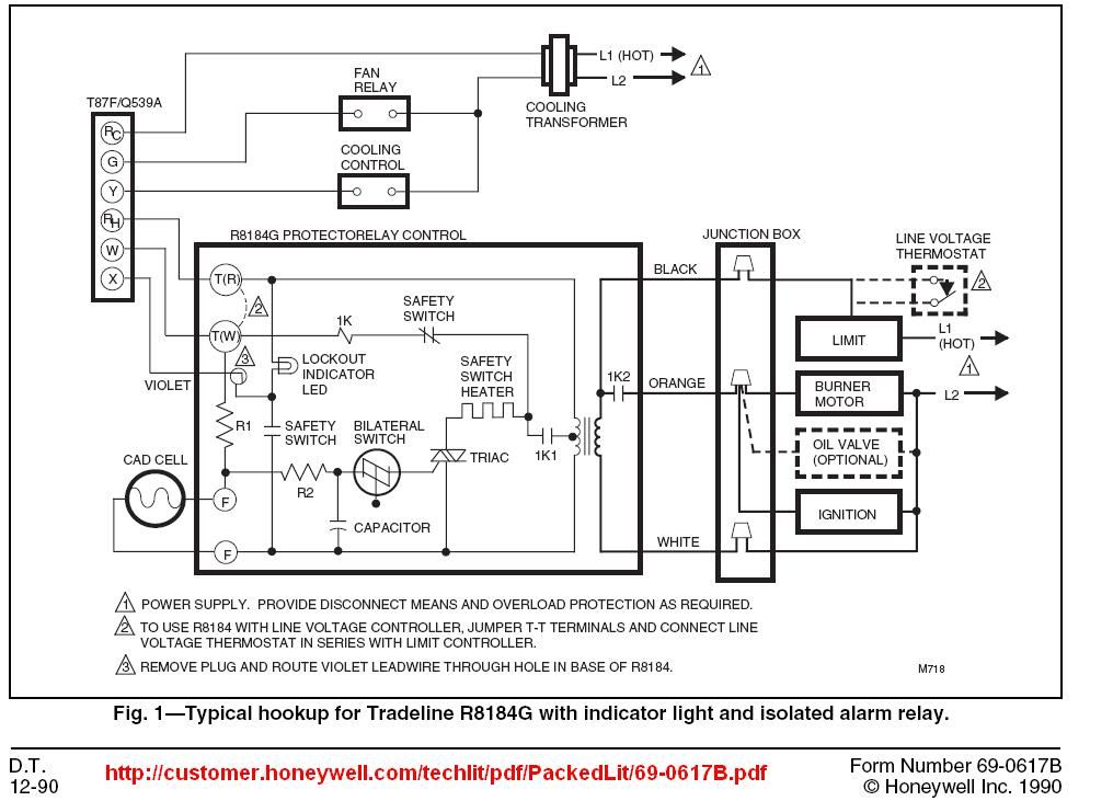
Wiring Diagram Honeywell Motorised Valve

Pin on access control wiring
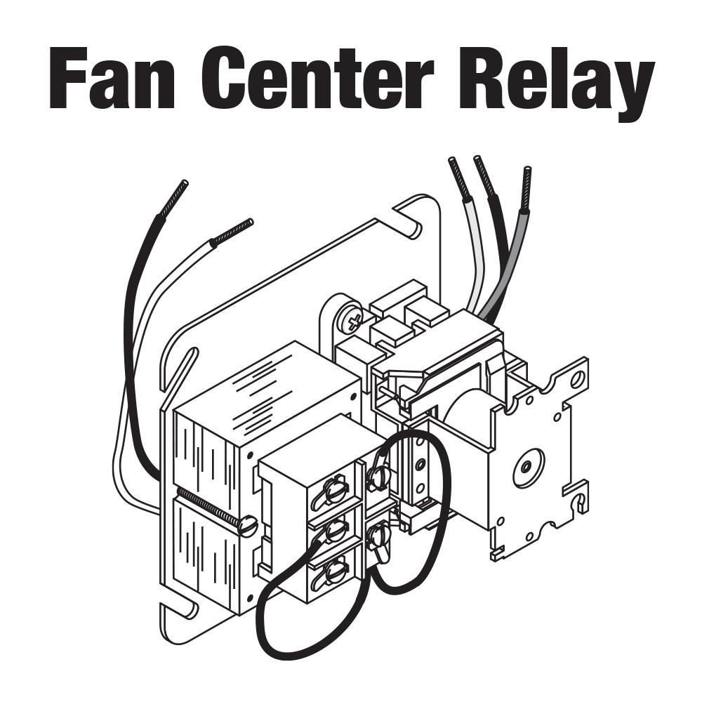
7 Photos How To Wire A Fan Center Relay And Description Alqu Blog
Fan Center Control Wiring schematic and wiring diagram

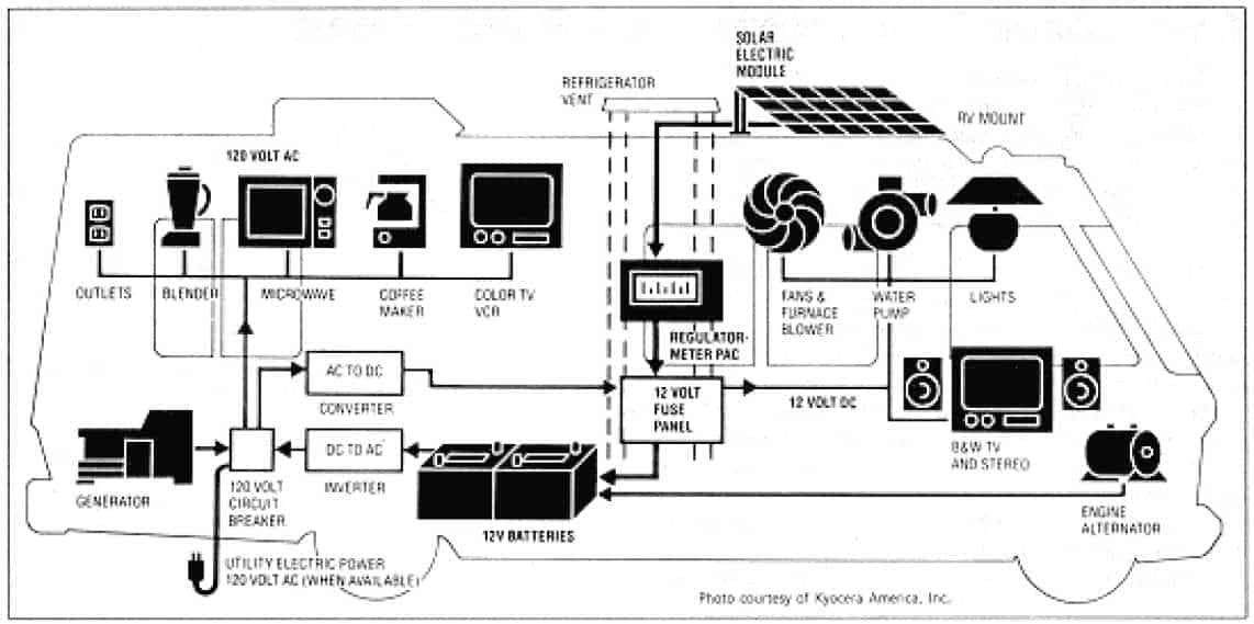
Various Common RV Problems That Most Owners Suffer Update 2017
Wiring Fan Control Relay HVAC DIY Chatroom Home Improvement Forum

Central Heating Wiring Diagrams Drayton Controls Biflo with LWC1 Wiring Centre Gas Support
Water Pump Wiring Diagram Single Phase

Heatmiser UFH wiring centre with TS Underfloor Heating

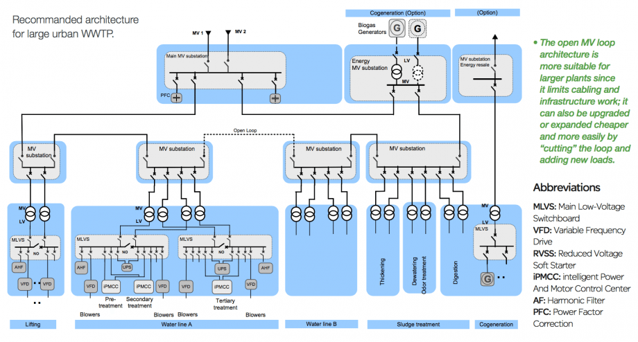
Electrical Distribution Architecture In Water Treatment Plants EEP
Central Heating Wiring Diagrams Drayton Controls Biflo with LWC3 Wiring Centre and Pump
35 Honeywell Fan Limit Switch Wiring Diagram Wire Diagram Source Information

Wiring boiler in control centre DIYnot Forums

Automatic Water Level Controller Wiring Diagram For 3 phase
Installer’s guide to UFH Wiring Ambiente


How To Wire A Fan Center Relay Sante Blog

Square D Mcc Bucket Wiring Diagram Gallery

How To Wire A Fan Center Relay Sante Blog
Johnson Controls Wiring Diagram LIZAMOI